
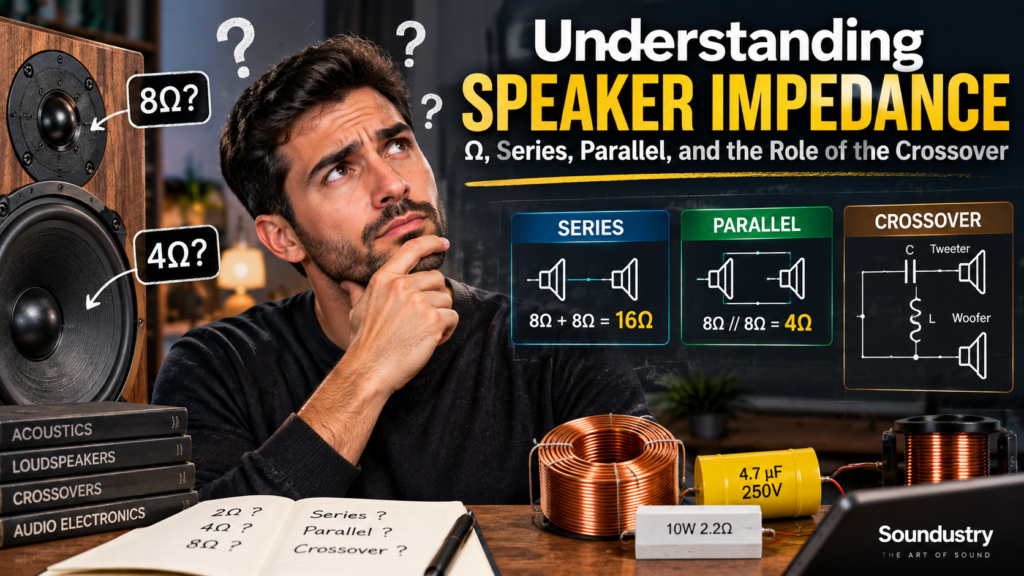
When you look at a Hi-Fi speaker, you will often find a specification such as 4 Ω, 6 Ω, 8 Ω, or 16 Ω.
But what does this value actually mean?
And more importantly, how can a speaker equipped with two, three, four, or even five drivers still be specified as a simple 8 Ω speaker?
To understand this, we first need to look at a fundamental electrical principle: Ohm’s law, and then at an even more important concept in audio: impedance.
1. Ohm’s Law: The Basics
Ohm’s law describes the relationship between voltage, current, and impedance in an electrical circuit.
For a simplified explanation:
At the same voltage, a lower impedance requires more current.
Let’s take a simple audio example using a voltage of 20 V RMS.
With an 8 Ω load:
20 V ÷ 8 Ω = 2.5 A RMS
With a 4 Ω load:
20 V ÷ 4 Ω = 5 A RMS
With a 2 Ω load:
20 V ÷ 2 Ω = 10 A RMS
So we can visualize it like this:
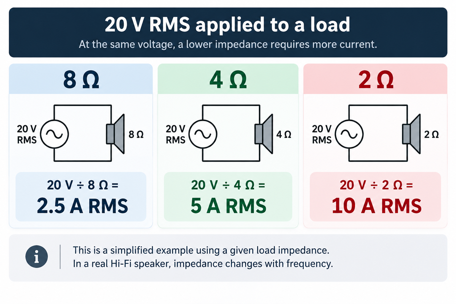
At the same voltage, cutting the impedance in half results in twice the current in this simplified example.
This is one of the reasons why a 4 Ω speaker can be more demanding for an amplifier than an 8 Ω speaker.
Note: This is a simplified example using a given load impedance. In a real Hi-Fi speaker, impedance changes with frequency.
2. An 8 Ω Speaker Is Not Simply an 8 Ω Resistor
This is an important distinction.
When a speaker is labeled 8 Ω, it does not mean that it simply contains a fixed 8 Ω resistor.
A loudspeaker has a voice coil, magnet, and moving diaphragm. The voice coil has electrical resistance and inductance, while the mechanical movement of the driver also affects its electrical behavior.
We therefore talk about impedance, represented by the letter Z, rather than simply resistance.
Most importantly:
The impedance of a loudspeaker varies with frequency.
A speaker labeled 8 Ω may therefore have a different impedance at 50 Hz, 500 Hz, 5 kHz, or 10 kHz.
A simplified impedance curve might look like this:
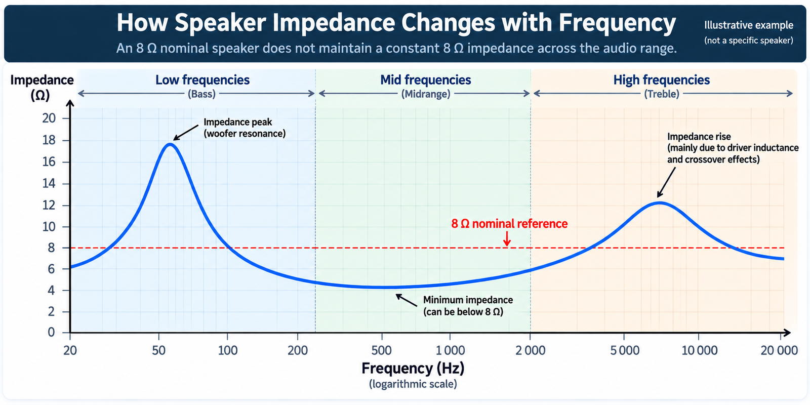
The 8 Ω specification is therefore generally a nominal impedance: a reference value used to characterize the speaker’s load.
It does not mean that the speaker remains exactly at 8 Ω throughout the entire audio range.
3. Why Is Impedance Important to the Amplifier?
The amplifier has to deliver electrical energy to the speaker.
The lower the load impedance, the more current the amplifier generally has to provide.
We can see this very simply:
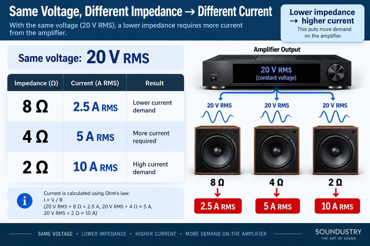
This does not mean that an amplifier always delivers exactly these values. In a real speaker, impedance changes with frequency, and the amplifier’s output voltage also depends on the listening level.
However, the example illustrates the principle:
At the same voltage, a lower impedance generally represents a more demanding load for the amplifier.
This is one reason why some amplifiers are designed to operate comfortably with 4 Ω loads, while others are better suited to speakers rated at 6 or 8 Ω.
4. What Happens When Several Drivers Are Used?
Now imagine two 8 Ω drivers.
The way they are connected completely changes the resulting load.
There are two basic possibilities:
- in series;
- in parallel.
However, these are simplified calculations. In a real loudspeaker, impedance varies with frequency.
5. Two 8 Ω Drivers in Series
In series, the impedances add together in the simplified case of two identical loads considered at the same frequency:
AMPLIFIER

  + ───── [ 8 Ω ] ───── [ 8 Ω ] ───── -
             DRIVER 1       DRIVER 2
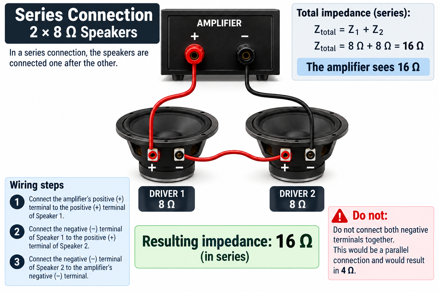
Simply:
8 Ω + 8 Ω = 16 Ω
Therefore:
2 identical 8 Ω loads
in series
        ↓
     16 Ω
With three identical 8 Ω loads in series:
8 + 8 + 8 = 24 Ω
The total load therefore becomes higher.
6. Two 8 Ω Drivers in Parallel
In parallel, the two drivers are connected across the same terminals:
              ┌──── [ 8 Ω ] ────┐
AMP + ────────┤                  ├────── AMP -
              └──── [ 8 Ω ] ────┘
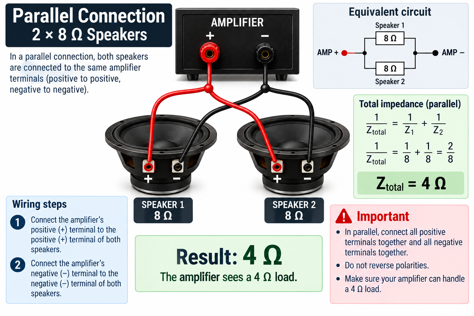
When the two loads are identical, the calculation becomes very simple:
8 Ω ÷ 2 = 4 Ω
Therefore:
2 identical 8 Ω loads
in parallel
        ↓
       4 Ω
With three identical 8 Ω loads in parallel:
8 Ω ÷ 3 ≈ 2.67 Ω
And with four:
8 Ω ÷ 4 = 2 Ω
This quickly shows why connecting several loads in parallel can become demanding for an amplifier.
The basic idea
SERIES

8 Ω ── 8 Ω

= 16 Ω


PARALLEL

       ┌── 8 Ω ──┐
       │         │
       └── 8 Ω ──┘

= 4 Ω
Note: These simple calculations apply to identical loads. They cannot be used directly to determine the impedance of a complete Hi-Fi loudspeaker.
7. So How Can a 3-Way Speaker Be 8 Ω?
This is probably the most interesting question.
Consider a typical 3-way speaker:
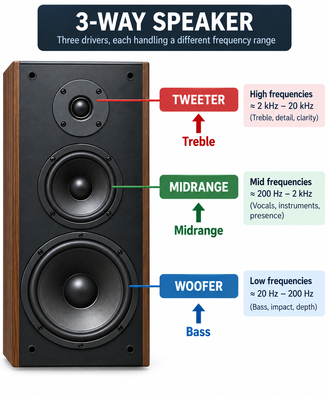
You might think:
“There are three 8 Ω drivers, so the speaker should be 24 Ω.”
But this reasoning does not apply to a complete 3-way loudspeaker.
Why?
Because the three drivers are not simply connected directly together.
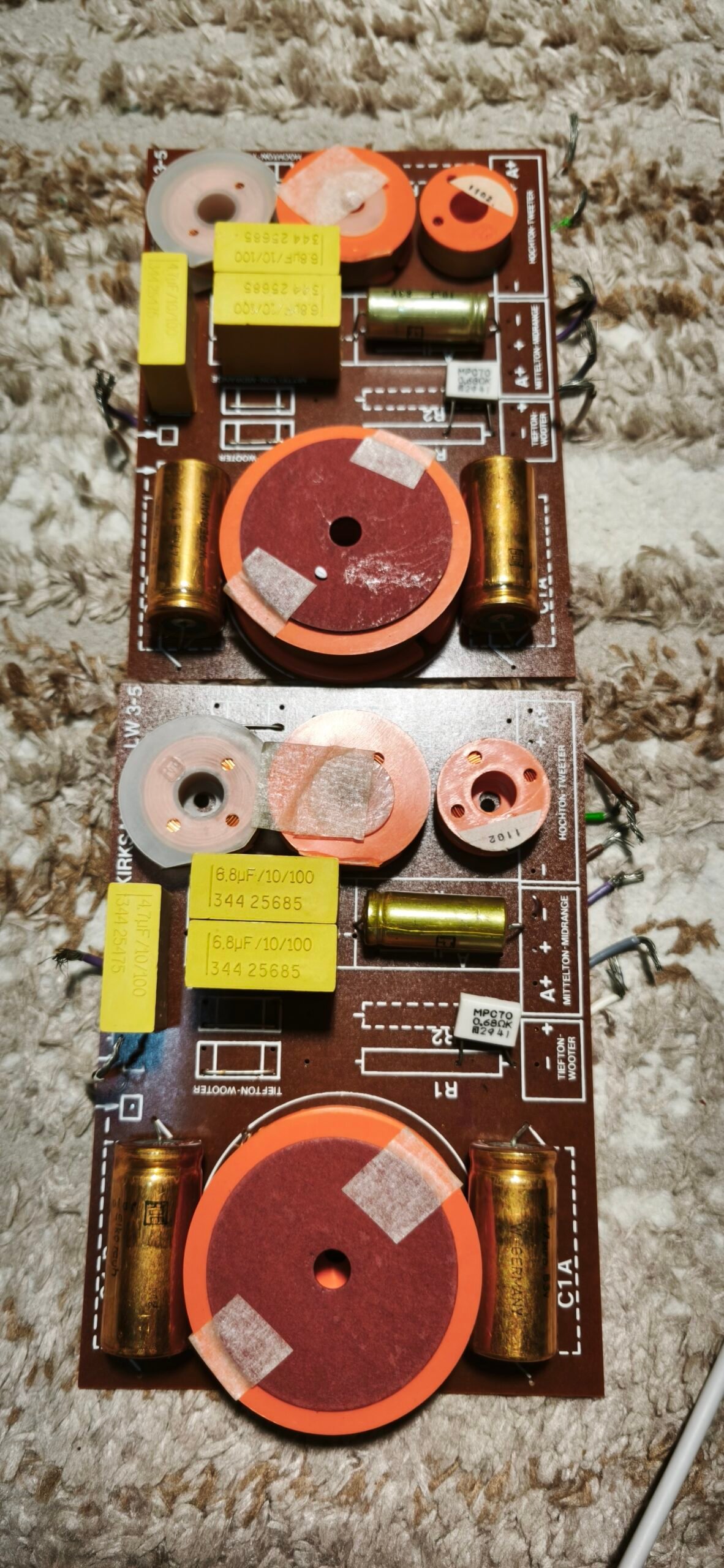
Between the amplifier and the drivers there is normally a crossover network.
8. The Role of the Crossover
The crossover is the circuit that distributes the audio signal among the different drivers.
In a 3-way speaker:
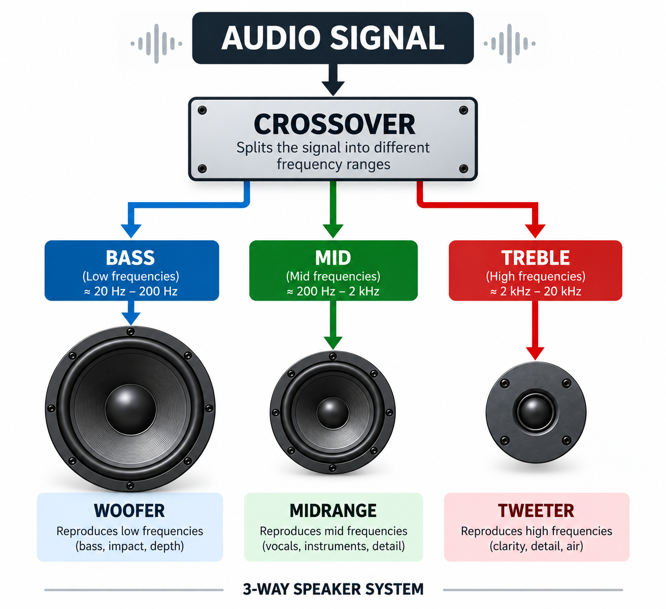
The woofer primarily handles low frequencies.
The midrange driver primarily handles midrange frequencies.
The tweeter primarily handles high frequencies.
However, it is important not to oversimplify this: a real crossover does not behave like a switch that suddenly turns a driver on or off at one frequency.
Around the crossover frequencies, the different drivers can operate simultaneously. Their responses gradually overlap according to the filter topology and slope.
A simplified representation looks like this:
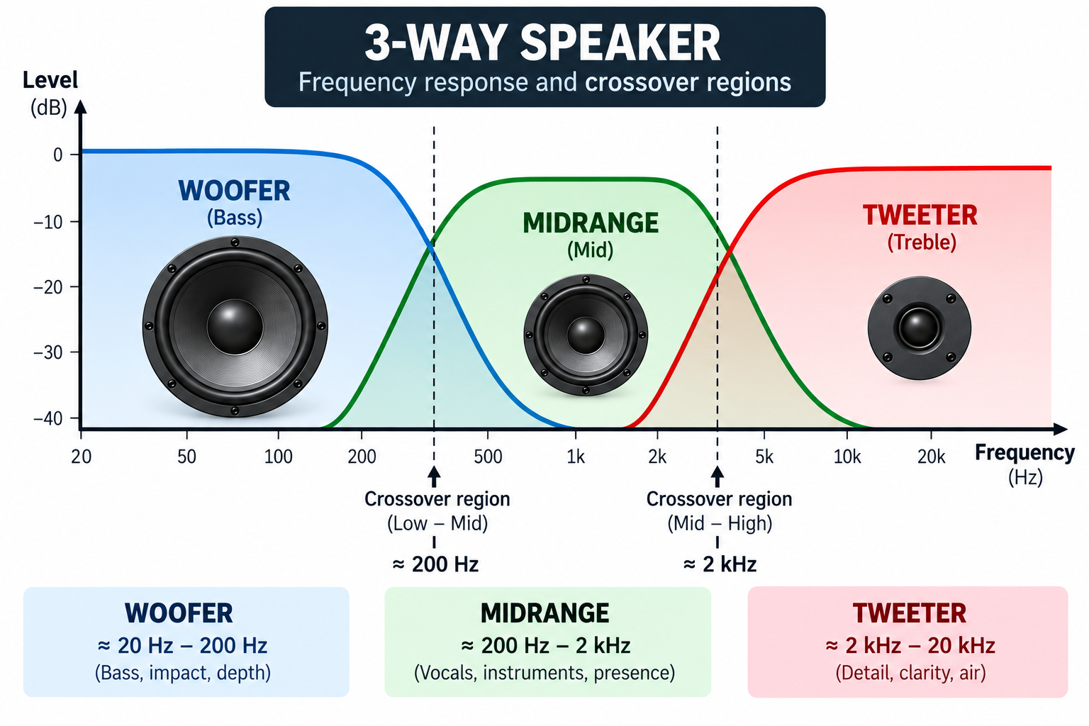
The crossover uses components such as inductors, capacitors, and resistors to control this distribution.
9. The Crossover Does More Than “Separate the Sound”
It is common to hear:
“The crossover separates the bass, midrange, and treble.”
That is true, but its role is much broader.
The crossover also contributes to:
- driver protection;
- frequency response;
- balance between the different drivers;
- relative output level;
- phase behavior;
- and the overall electrical behavior of the speaker.
In other words:
The crossover directly contributes to the way the amplifier sees the speaker.
10. Why Don’t Three 8 Ω Drivers Simply Make 24 Ω?
Because the three drivers do not simply present their full impedance to the amplifier across the entire audio range.
The crossover behaves differently depending on frequency.
In simplified terms:
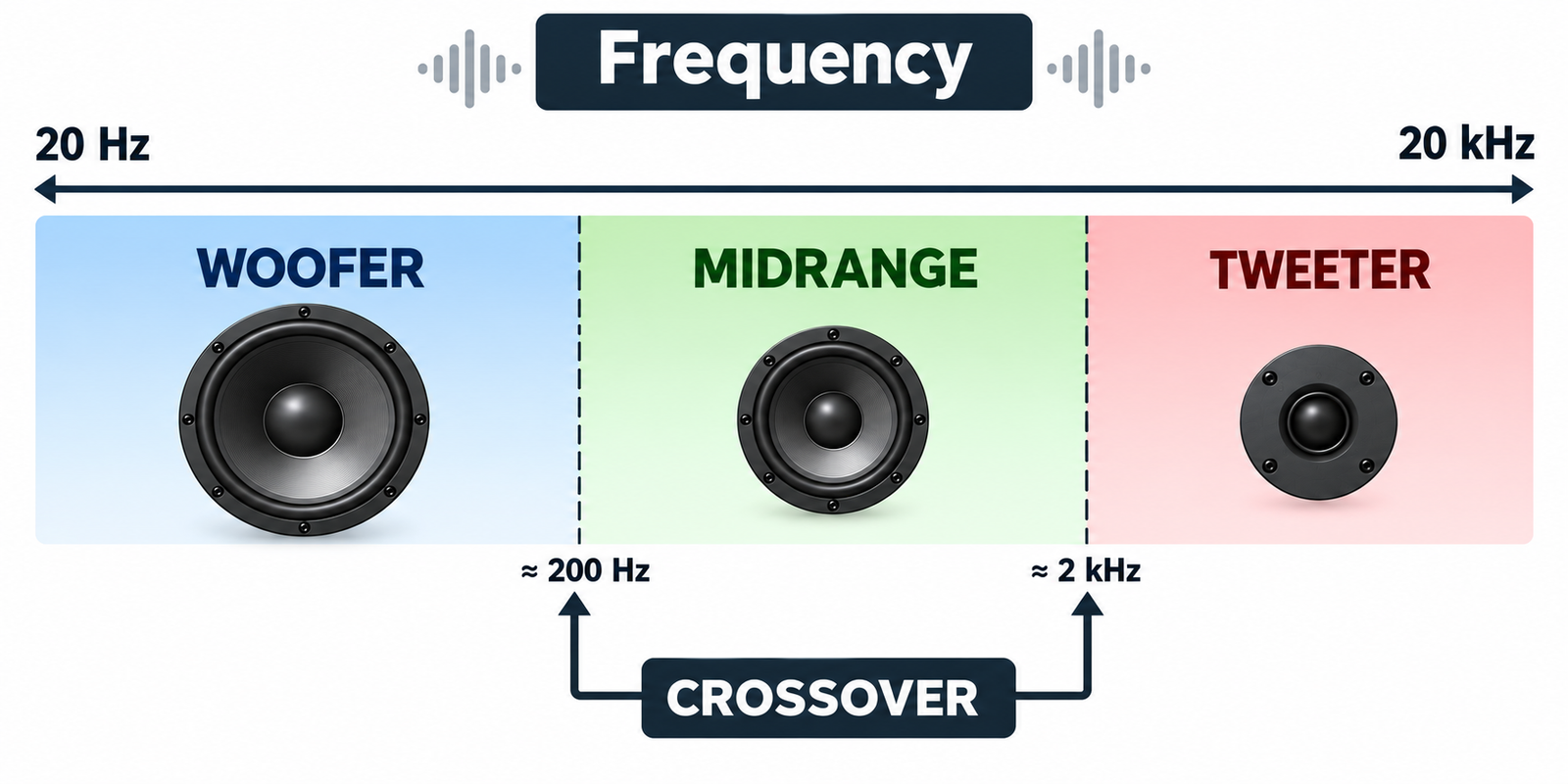
At low frequencies, the crossover primarily favors the woofer.
In the midrange, it primarily favors the midrange driver.
At high frequencies, it primarily favors the tweeter.
The transition regions overlap around the crossover frequencies.
Therefore, the amplifier does not simply see:
8 Ω + 8 Ω + 8 Ω = 24 Ω
It sees the electrical behavior of the complete system: drivers + crossover.
11. A Simplified 3-Way Example
Imagine:
Woofer   → 8 Ω
Midrange → 8 Ω
Tweeter  → 8 Ω
Without a crossover, we could not simply describe the complete system as an 8 Ω speaker.
But with a crossover:
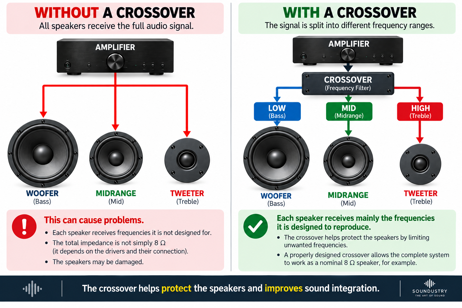
The designer selects the component values and network topology to achieve the desired electrical and acoustic behavior.
The resulting speaker can therefore have a nominal impedance of 8 Ω.
12. What About 2-Way Speakers?
The principle is exactly the same.
A typical 2-way speaker has:
- a woofer or midwoofer;
- a tweeter;
- a crossover.
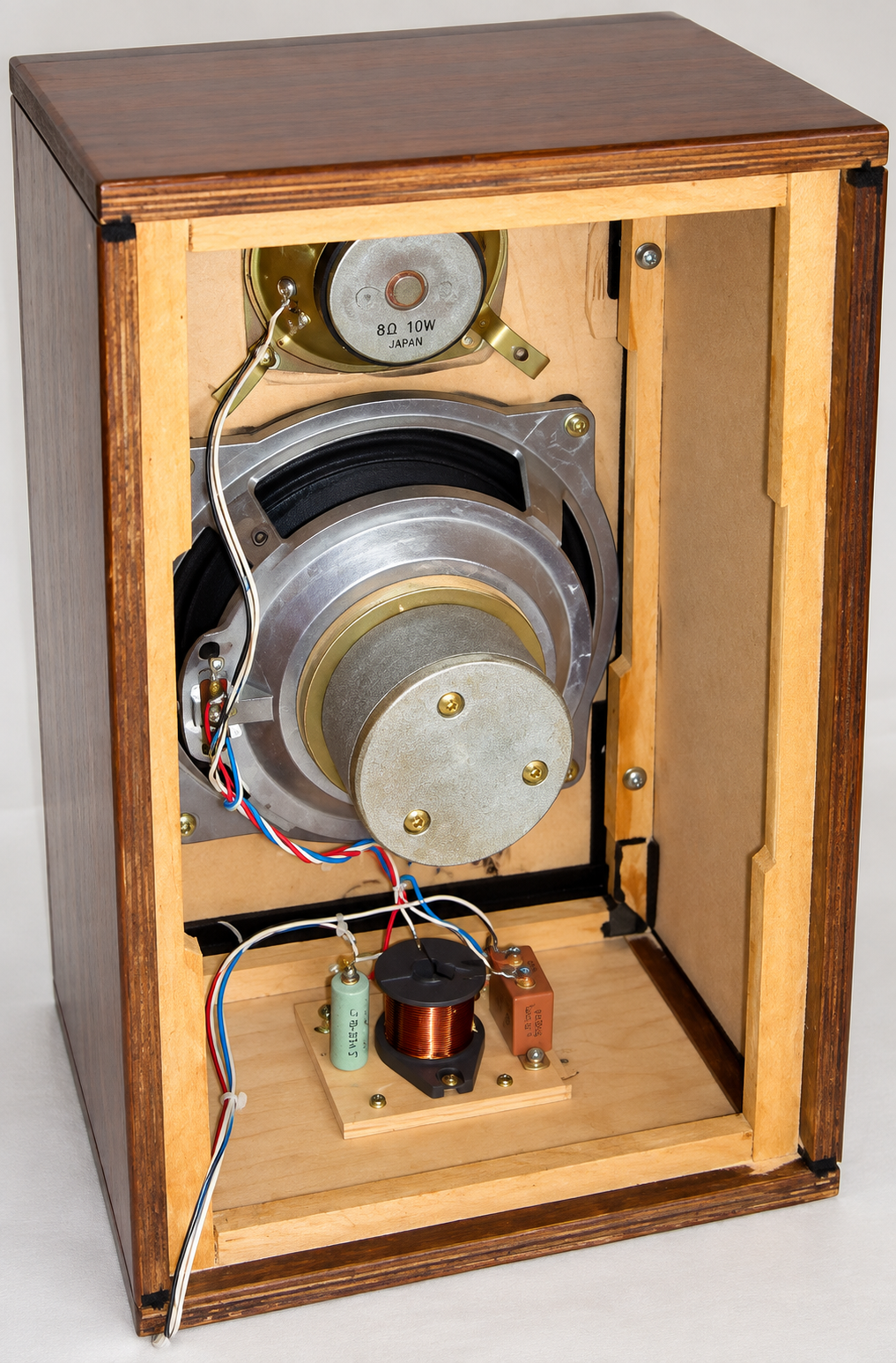
It can perfectly well be specified as:
8 Ω nominal
even though it contains two drivers.
13. What About 4-Way or 5-Way Speakers?
The same principle applies.
A 5-way speaker may use several specialized drivers:
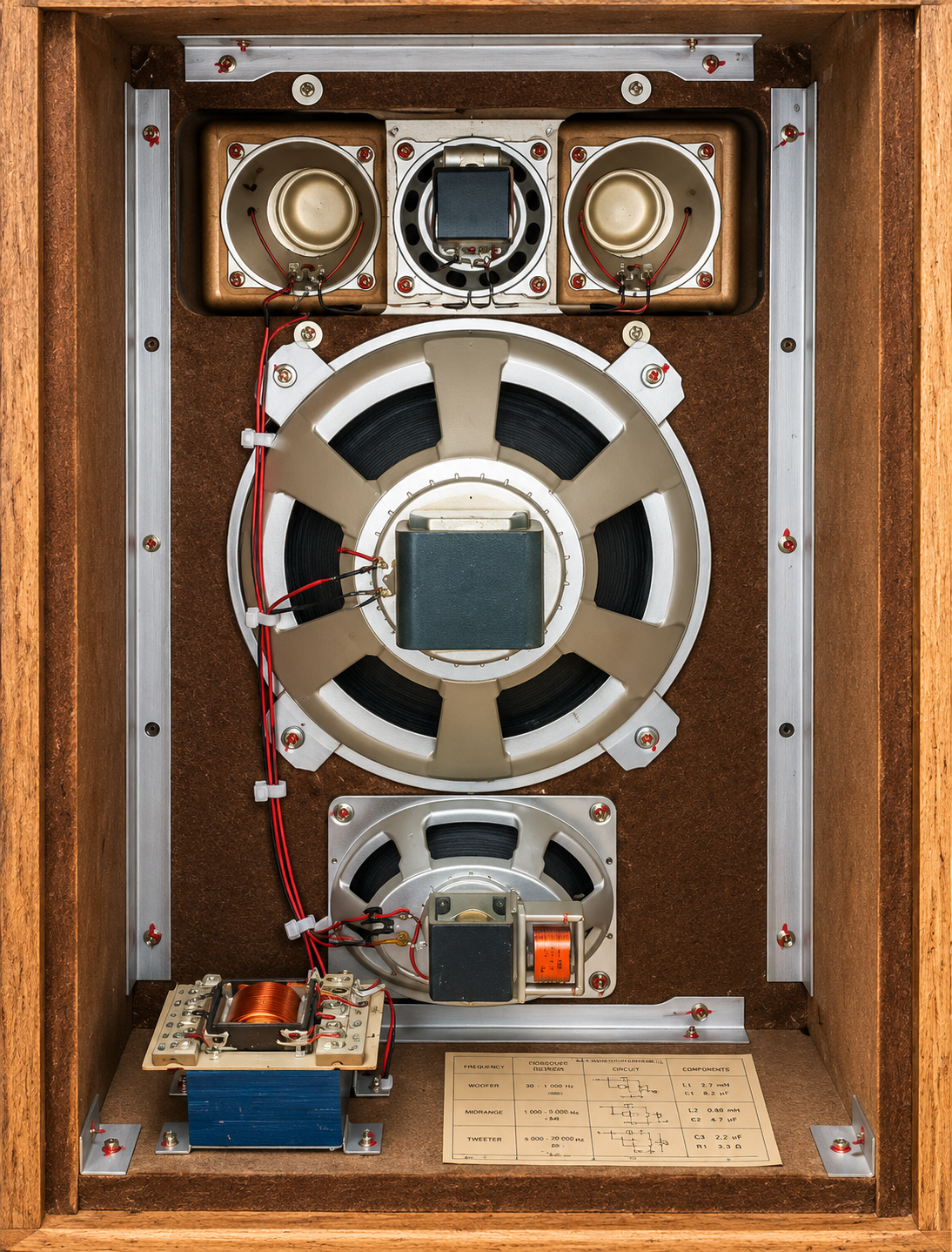
                    CROSSOVER
                        │
       ┌────────────────┼────────────────┐
       │        │       │       │        │
     SUB-BASS  BASS    MID     MID     TREBLE
       │        │       │       │        │
       ▼        ▼       ▼       ▼        ▼
      HP1      HP2     HP3     HP4     TWEETER
You might be tempted to calculate:
8 + 8 + 8 + 8 + 8 = 40 Ω
But that is not how the impedance of a multi-way speaker is determined.
The crossover distributes the frequencies and influences the overall electrical load.
A 5-way speaker can therefore still be specified as:
8 Ω nominal
14. The Drivers Don’t Even Have to Have the Same Impedance
This is another important point.
In a real multi-way speaker, you might find:
Woofer   → 4 Ω
Midrange → 8 Ω
Tweeter  → 6 Ω
This does not automatically mean that the speaker has an impedance of:
4 + 8 + 6 = 18 Ω
The crossover is designed around the actual characteristics of the drivers.
The designer can use different component values and network configurations to achieve the desired behavior.
Therefore, it is the complete system that matters.
15. How Do Capacitors and Inductors Work?
You do not need to be an electronics engineer to understand the basic idea.
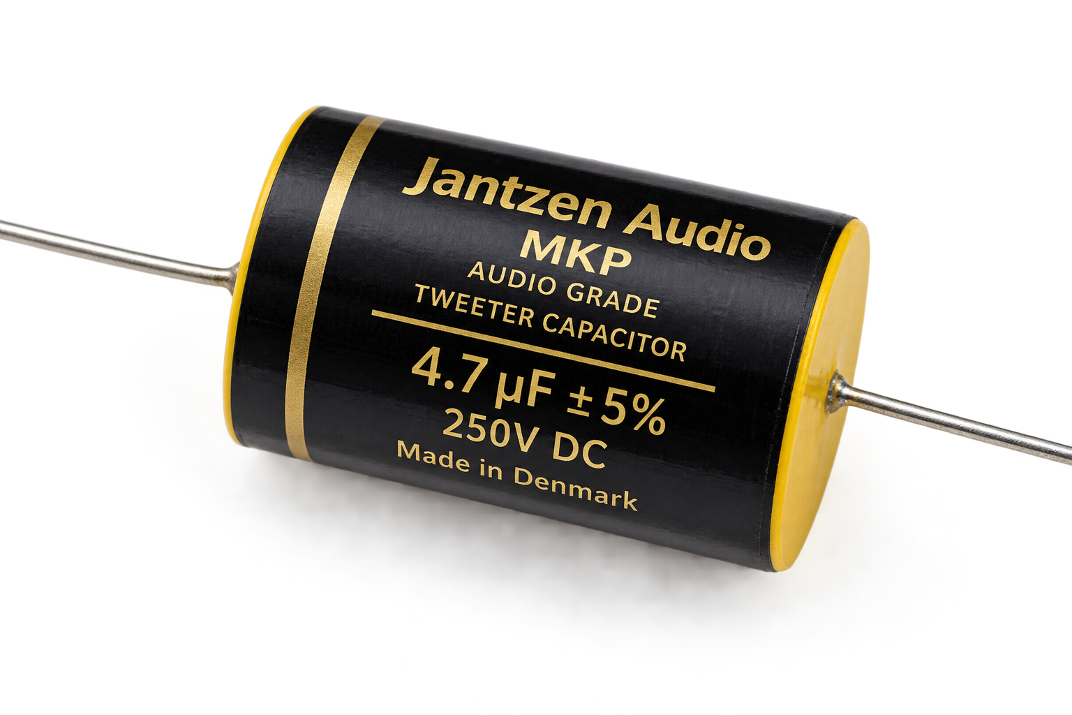
The Capacitor
In a conventional high-pass filter, a capacitor can be used to favor high frequencies and attenuate low frequencies.
Simplified example:
AMP ───► CAPACITOR ───► TWEETER
              │
              ▼
          High frequencies
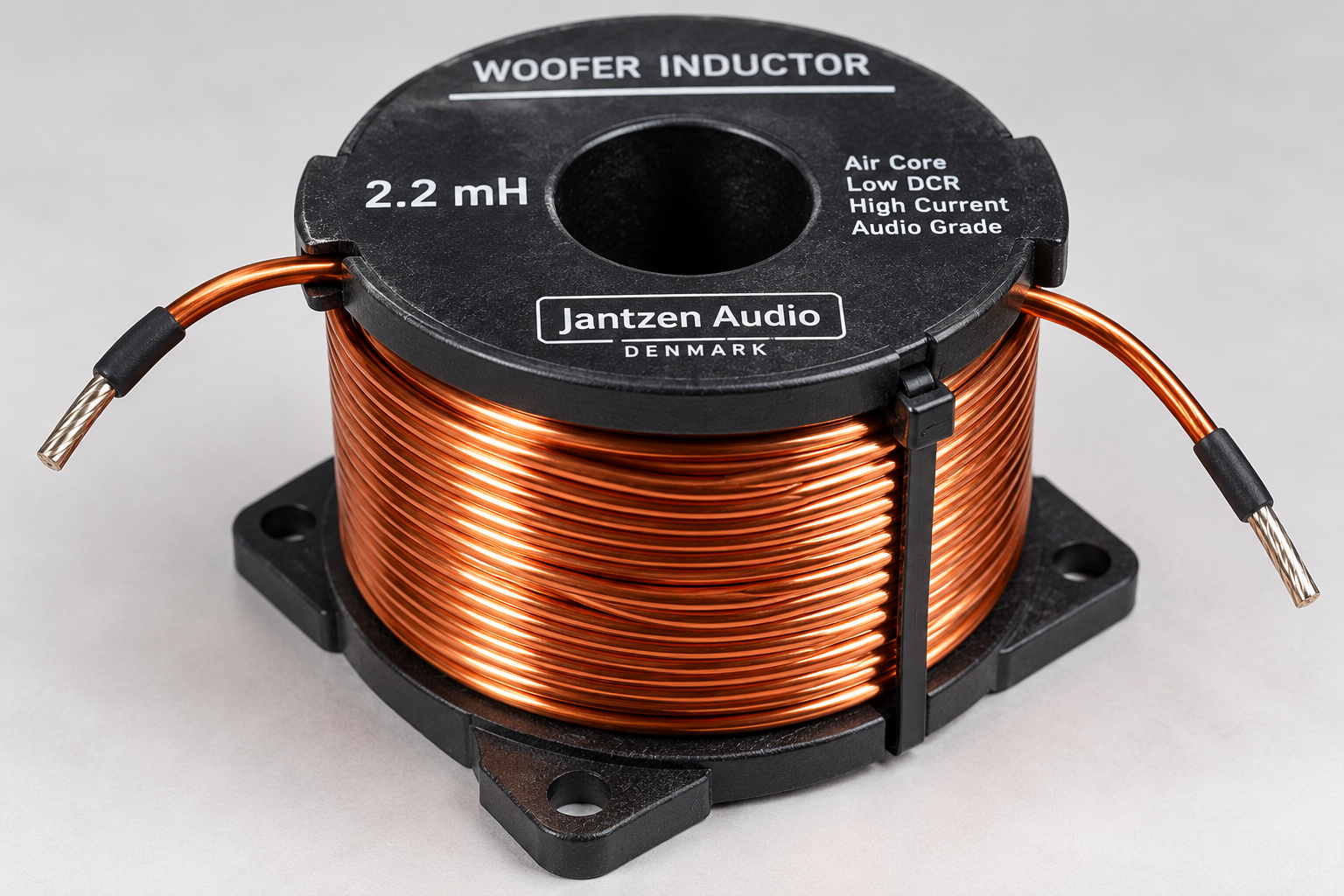
The Inductor
In a conventional low-pass filter, an inductor can be used to favor low frequencies and progressively attenuate high frequencies.
AMP ───► INDUCTOR ───► WOOFER
             │
             ▼
          Low frequencies
By combining these components, the designer can create much more complex filter networks.
16. Why Does the Tweeter Particularly Need a Crossover?
A tweeter is designed to reproduce high frequencies.
Sending a large amount of low-frequency energy to it can cause excessive diaphragm movement and expose the driver to energy it was not designed to handle.
The crossover therefore also contributes to tweeter protection.
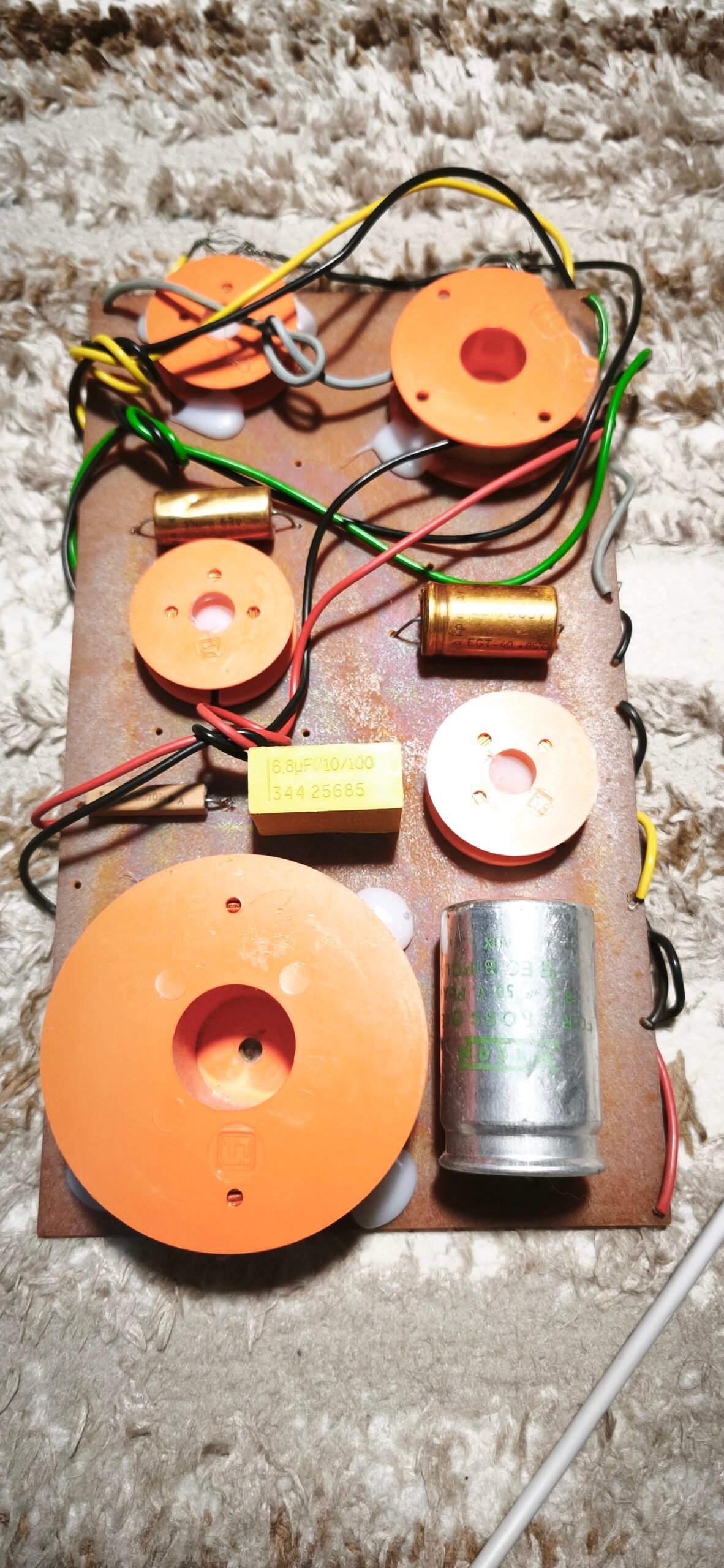
FULL AUDIO SIGNAL
       │
       ▼
    CROSSOVER
       │
       ├──────────────► WOOFER
       │                 Bass
       │
       └──────────────► TWEETER
                         Treble
This is why a crossover is both an electrical filter and an essential part of the acoustic integration of a passive multi-way loudspeaker.
17. Why Can Two 8 Ω Speakers Be Very Different?
This is particularly important in Hi-Fi.
Two speakers can both be labeled:
8 Ω
yet behave very differently.
For example:
SPEAKER A

8 Ω nominal
Minimum impedance: approximately 6 Ω


SPEAKER B

8 Ω nominal
Minimum impedance: approximately 3 Ω
The second speaker may be significantly more demanding for the amplifier.
Why?
Because 8 Ω nominal does not mean that the impedance remains constantly at 8 Ω.
It can rise or fall depending on frequency.
18. Minimum Impedance Can Be More Informative Than Simply “8 Ω”
When choosing an amplifier for a speaker, it is therefore useful to know:
- its nominal impedance;
- its minimum impedance;
- its impedance curve, when available;
- and the amplifier’s ability to supply the required current.
An 8 Ω speaker with a relatively high minimum impedance may be fairly easy to drive.
Another speaker also rated at 8 Ω but dropping significantly lower may require considerably more current.
19. Series or Parallel: Why Does It Matter?
Let’s return to our simple example.
Series
AMP + ── [ 8 Ω ] ── [ 8 Ω ] ── AMP -
For two identical loads:
8 + 8 = 16 Ω
The impedance increases.
Parallel
             ┌── [ 8 Ω ] ──┐
AMP + ───────┤              ├──── AMP -
             └── [ 8 Ω ] ──┘
For two identical loads:
8 ÷ 2 = 4 Ω
The impedance decreases.
This already shows why the way drivers are connected is extremely important.
However, in a real Hi-Fi speaker, we must also consider the crossover and the fact that impedance changes with frequency.
20. A Simple Analogy for Understanding the Amplifier
We can use a very simplified analogy.
Imagine the amplifier as a source capable of pushing electrical current toward the speaker.
An 8 Ω load represents a certain level of difficulty.
A 4 Ω load requires more current.
A 2 Ω load requires even more.
HIGHER IMPEDANCE

8 Ω
 │
 ▼
AMPLIFIER
 → relatively moderate current


LOWER IMPEDANCE

4 Ω
 │
 ▼
AMPLIFIER
 → higher current


VERY LOW IMPEDANCE

2 Ω
 │
 ▼
AMPLIFIER
 → much higher current
This analogy is intentionally simplified because the impedance of a real loudspeaker depends on frequency and many other parameters.
21. What Should You Remember About Ω?
When you see 8 Ω on the back of a speaker, do not simply think:
“This speaker contains an 8 Ω resistor.”
Think instead:
“This speaker is designed to present an approximately 8 Ω nominal load to the amplifier, but its actual impedance varies with frequency.”
And when a speaker contains three drivers:
Woofer
Midrange
Tweeter
do not simply calculate:
8 + 8 + 8 = 24 Ω
The crossover fundamentally changes the behavior of the system.
22. The Key Diagram
This is the simplest way to visualize how a 3-way speaker works:
                       AMPLIFIER
                            │
                            │
                            ▼
                    ┌───────────────┐
                    │    CROSSOVER  │
                    │               │
                    │   Capacitors  │
                    │   Inductors   │
                    │   Resistors   │
                    └───────────────┘
                       │     │     │
                       │     │     │
                     LOW    MID   HIGH
                       │     │     │
                       ▼     ▼     ▼
                    WOOFER MIDRANGE TWEETER
                       │     │     │
                       ▼     ▼     ▼
                      BASS MIDRANGE TREBLE
The amplifier therefore does not simply see several resistors connected together.
It sees:
drivers + crossover + wiring + frequency-dependent behavior.
This combination determines the electrical load presented to the amplifier.
23. Quick Summary
Two identical loads in series
8 Ω + 8 Ω = 16 Ω
Two identical loads in parallel
8 Ω ÷ 2 = 4 Ω
Three identical 8 Ω loads in parallel
8 Ω ÷ 3 ≈ 2.67 Ω
A 3-way speaker
Woofer + Midrange + Tweeter
             ↓
         CROSSOVER
             ↓
      OVERALL IMPEDANCE
             ↓
        e.g. 8 Ω nominal
Most importantly
The number of drivers does not directly determine the total impedance of a loudspeaker.
The crossover, wiring, individual driver impedances, and frequency-dependent behavior all have to be considered.
Conclusion
Understanding Ω helps us understand the relationship between a Hi-Fi speaker and its amplifier.
Ohm’s law shows us one essential principle: for the same voltage, a lower impedance requires more current.
But a Hi-Fi speaker is not simply a resistor.
Its impedance varies with frequency, and in a 2-, 3-, 4-, or 5-way speaker, the crossover network plays a fundamental role.
It distributes frequencies between the different drivers, contributes to driver protection, balances their output levels, and influences the overall electrical behavior of the speaker.
This is why a speaker equipped with three 8 Ω drivers is not simply a 24 Ω speaker.
The designer does not simply add the individual driver impedances. Instead, the drivers and crossover network are designed as one complete system to achieve the desired acoustic and electrical behavior.
A multi-driver speaker can therefore perfectly well be specified as an 8 Ω nominal speaker.
And this is the key point to remember:
When you connect a Hi-Fi speaker to an amplifier, the amplifier does not simply “see” the number of drivers. It sees the electrical impedance of the complete speaker system, and that impedance changes with frequency.
This is one of the reasons why designing a good Hi-Fi loudspeaker is far more complex than it may initially appear.